| Some of the links on my blog are affiliate links. This means that if you click on the link and buy the item, I will receive a commission at no extra cost to you. My opinion remains unaffected. |
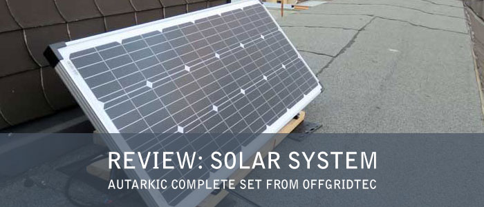
In this article I have tested for you a solar system in a complete set and show you my experiences. I received the Autarkic S-Master 100W Solar System - 600W AC Output 12V 230V* from the company Offgridtec for testing, with which I would like to thank once again very much.
Even though the set was given me for testing, this has no influence on my test result. I am neither paid nor sponsored by Offgridtec. The test period was more than one year.
Table of Contents
- 1 The main features
- 2 Components of the Offgidtec Autarkic S-Master Solar Set
- 2.1 Offgridtec 100 Watt 12V Solar Panel
- 2.2 Steca 20A Solar Charge Controller PR 2020
- 2.3 Offgridtec AGM Battery 101Ah 12V
- 2.4 Sine Wave Inverter 12V to 230V, 600 W (Solartronics)
- 2.5 8m Module connection cable to solar charge controller (2x6mm²)
- 2.6 1.5m Battery cable with flat fuse holder, fuse and battery terminal clamps
- 2.7 20A Car flat fuse 6-32V
- 2.8 Victron Battery Protect BP-65 12V 24V / 65A
- 2.9 Battery connection cable with 80A fuse between Battery Protect and battery
- 2.10 Universal module holder for 12V solar modules floor- wall mounting
- 3 Installation of the Solar Set
- 4 Usability and Installation
- 5 Control behavior
- 6 Result after one year: electrical energy generated
- 7 Conclusion
The main features
Who does not dream of producing their own electricity and become a little more self-sufficient? In November 2017, I received the Autarkic S-Master 100W Solar System – 600W AC Output 12V 230V and was able to test the system intensively for over a year.
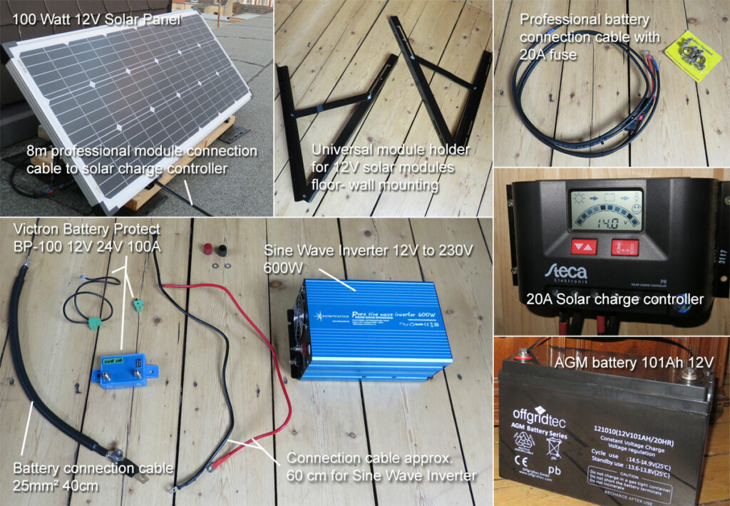
The solar set consists of the following components, which I will introduce in more detail afterwards:
- 1 x 100 Watt 12V Solar Panel from Offgridtec*
- 1 x 20A solar charge controller PR 2020 from Steca with display*
- 1 x Sine wave inverter 12V to 230V from Solartronics 600W*
- 1 x Offgridtec AGM battery 101Ah 12V*
- 1 x 8m Professional module connection cable to solar charge controller (2x6mm²)*
- 1 x Professional battery connection cable with 20A fuse*
Recommendations and accessories:
- 1 x Victron Smart Battery Protect BP-65 12V 24V 65A*
- 1 x 80A 32V MEGA-Fuse*
- 1 x Battery connection cable 25mm² 40cm*
- 1 x Universal module holder for 12V solar modules floor- wall mounting*
Components of the Offgidtec Autarkic S-Master Solar Set
Offgridtec 100 Watt 12V Solar Panel
The 100 Watt solar panel has high quality monocrystalline solar cells and is needed for charging the 12V battery. Monocrystalline solar cells are more expensive compared to polycrystalline solar cells, but have up to 20% higher efficiency due to the high silicon content.
Update 03/21/2021: The current version of the set includes the Offgridtec® 130W MONO 12V Solar Panel*, which is slightly larger at 130W.
* Affiliate Link - Last updated prices on 2024-04-18 / Picture source: Amazon affiliate program
The frame of the solar panel is made of anodized aluminum (Eloxal process), which means refinement of the surface structure and results in an extremely hard and scratch-resistant surface of the frame.
Furthermore, the module has a specially hardened resistant tempered solar glass, which allows as much solar radiation as possible to enter the collector. More technical data can be found in the data sheet for the solar module.
* Affiliate Link - Last updated prices on 2024-04-18 / Picture source: Amazon affiliate program
Steca 20A Solar Charge Controller PR 2020
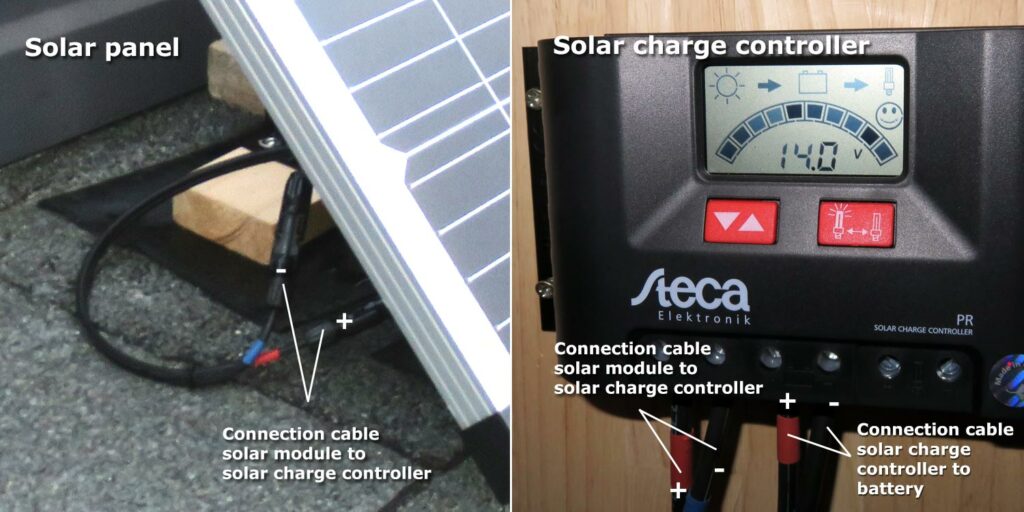
The Steca solar charge controller is the heart of the solar system and has a maximum charging current of 20A. The module connection cables from the solar module go into the solar controller and the battery connection cables to the battery go out.
Update 03/21/2021: In the current version of the set is the Offgridtec PWM Pro Charge Controller 12V/24V 20A USB*, which has a very good rating and is much cheaper (costs almost half of the Steca 20A solar charge controller PR 2020):
* Affiliate Link - Last updated prices on 2024-04-18 / Picture source: Amazon affiliate program
Furthermore, the current version of the complete set includes a external temperature sensor* for the Offgridtec PWM Pro charge controller, which is highly recommended. The sensor detects the battery temperature and forwards this information to the charge controller. The installation of the external sensor allows the charge controller to calculate the optimal charge current depending on the battery temperature.
* Affiliate Link - Last updated prices on 2024-04-18 / Picture source: Amazon affiliate program
The solar controller provides information about the state of charge of the battery and has integrated important mechanisms to protect the solar system. These include:
- Protection against reverse polarity connected solar modules
- Protection against loads connected to the load output with polarity reversal
- Protection against battery connected with reverse polarity
- Charge and discharge of the battery are prevented
- Short-circuit protection at module input
- Short circuit protection at load output
- Protection against too high charging current
- No-load test during operation without battery or load
- Reverse current protection
- Overvoltage and undervoltage protection
- Overtemperature protection
- Deep discharge protection / overcharge protection (deep discharge protection only for directly connected loads with 12V DC!)
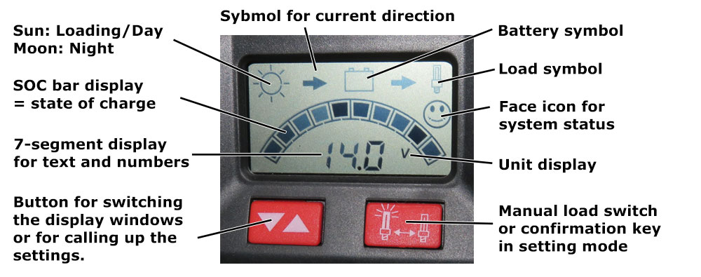
Additionally a lot of important informations are shown on the integrated display (see figure 3).
It is also possible to call up the following operating states:
- SOC Window: Display of the state of charge day/night in percent.
- Voltage window (battery symbol): display of the battery voltage measured by the controller
- Module current (sun symbol): display of the output current of the solar module
- Charge current (sun with arrow on battery): display of the charge current into the battery in amperes (A)
- Load current (battery with arrow on lamp): display of the current drawn from the load output in amperes (A)
- Ah – counter battery charge (sun with arrow): display of the total Ah charged into the battery since first installation or last reset
- Ah – Discharge counter (arrow on lamp): display of the total Ah discharged via the load output since initial installation or last reset
- Prewarning deep discharge protection (SOC indicator bar flashes), face is still friendly
- Load disconnection (deep discharge protection active, bar indicator flashes in SOC mode – but not in voltage mode, battery symbol, right arrow, load symbol and alphanumeric value): The face looks sad
Only 12V and 24V loads (right-hand pair of load outputs) may be connected directly to the Steca PR 2020. For 230V consumers, the sine wave inverter is used.
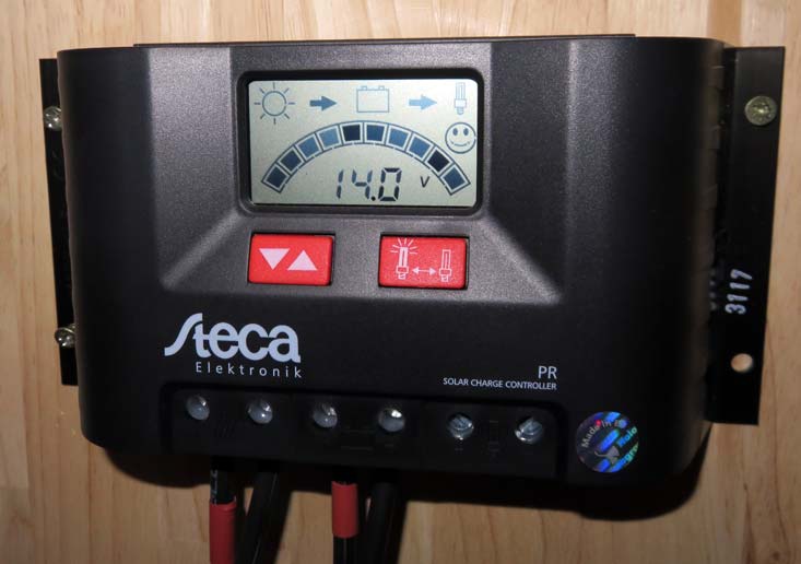
In addition, only lead-acid batteries with liquid electrolytes and sealed lead-acid batteries, AGM, GEL may be used. Here you can find the instruction manual for the Steca PR2020.
* Affiliate Link - Last updated prices on 2024-04-18 / Picture source: Amazon affiliate program
Offgridtec AGM Battery 101Ah 12V
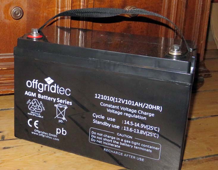
In the complete set of Offgridtec is an AGM battery included, which is specially designed for the use of solar systems and extremely cycle resistant. AGM batteries can not leak, are maintenance-free and have a life expectancy of about 8 – 10 years.
Offgridtec states that the purchase of an AGM battery is more expensive than a lead-acid battery, but this is offset due to the higher maintenance intensity and lower life expectancy of lead-acid batteries. By the way, the battery weighs 31.6 kg and is pretty heavy. Click here for the data sheet of the AGM battery.
Important note: You can return your battery after use to the point of sale or to a local municipal collection point. Batteries and rechargeable batteries do not belong in the household waste! The return can be done at Offgridtec.com or the public collection points of the municipality.
* Affiliate Link - Last updated prices on 2024-04-18 / Picture source: Amazon affiliate program
Sine Wave Inverter 12V to 230V, 600 W (Solartronics)
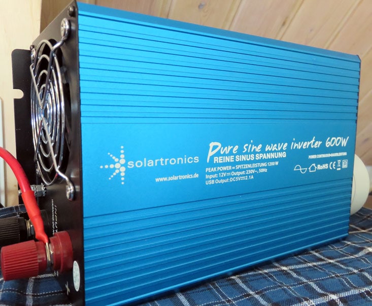
The sine wave inverter (also called voltage converter) converts the 12V DC voltage from the battery into 230V (50Hz) AC voltage in our solar system, so that normal household appliances can be operated with a rated voltage of 230V. The voltage converter has a Schuko socket and generates a real sine wave.
Update 03/21/2021: The current version of the set includes the Offgridtec® PSI Sine Wave Inverter 500W 1000W 12V to 230V*.
* Affiliate Link - Last updated prices on 2024-04-18 / Picture source: Amazon affiliate program
The maximum specified continuous power in AC mode is 600W according to the manufacturer, and there is a fan that protects against overheating. The scope of delivery includes two connection cables of just under 60cm in length.
* Affiliate Link - Last updated prices on 2024-04-18 / Picture source: Amazon affiliate program
8m Module connection cable to solar charge controller (2x6mm²)
The module connection cable is attached to the solar module and the solar controller. It is a 2-wire solar cable with a matching MC4 connector for the solar modules and wire end sleeves for the charge controller.
The length of the double-insulated connection cable is 8 meters and the wire cross-section is 6mm². According to the manufacturer, it is resistant to UV, ozone, weather and water.
* Affiliate Link - Last updated prices on 2024-04-18 / Picture source: Amazon affiliate program
1.5m Battery cable with flat fuse holder, fuse and battery terminal clamps
The battery cable with fuse switch is necessary to connect the battery to the solar charge controller. The cable has battery terminals and a 30A fuse. Sometimes other fuse sizes are included in the delivery.
The cable is equipped with wire end sleeves for connection to the charge controller, and with M8 ring lugs for connection to the battery or battery terminals. The battery pole terminals are included in the scope of delivery.
* Affiliate Link - Last updated prices on 2024-04-18 / Picture source: Amazon affiliate program
20A Car flat fuse 6-32V
I installed a 20A fuse in the flat fuse switch of the battery cable because the Steca solar charge controller has a maximum module current of 20A. 20A is also recommended by Offgridtec.
If the battery cable does not include a 20A fuse, it can be purchased for a few euros. It is included in the solar complete set. The prices for a 20A fuse vary greatly. 50 pieces cost around 8€ and a single one from 30 cents to 3€. Here it is important to compare prices.
* Affiliate Link - Last updated prices on 2024-04-18 / Picture source: Amazon affiliate program
Victron Battery Protect BP-65 12V 24V / 65A
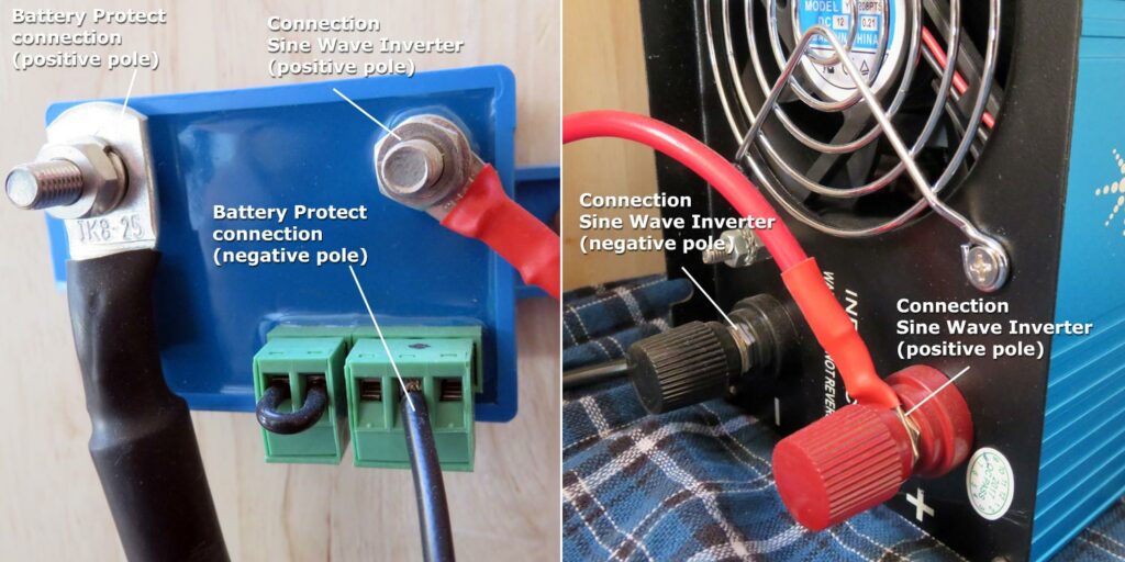
Since the deep discharge protection of the solar charge controller for the battery is only effective for loads that are directly connected to the charge controller (loads with 12V, DC), it is recommended to place the Victron Battery Protect 65A between sine wave inverter (load with 230V, AC) and the battery to ensure deep discharge protection here as well.
Update 03/21/2021: The Batteriy Protect is still not in the complete set from Offgridtec. Nevertheless, there are important news here. The Smart BatteryProtect BP-65* has an integrated Bluetooth interface, so that all required on/off thresholds can be configured, monitored, updated and diagnosed via the Victron Connect app (Google Playstore and Apple Appstore).
* Affiliate Link - Last updated prices on 2024-04-19 / Picture source: Amazon affiliate program
For the connection, we still additionally need the connection cable with fuse presented in the next section. Click here for the data sheet of the old Victron Battery Protect and here for the smart version of the Victron Battery Protect.
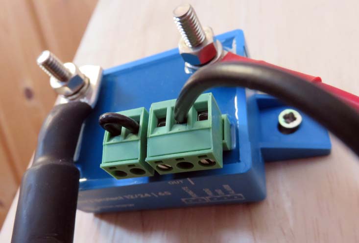
Battery connection cable with 80A fuse between Battery Protect and battery
This battery connection cable, with a wire cross-section of 25 mm² is needed to connect the Victron Battery Protect BP-65 with the battery. In the assembly instructions I will go into this again so that it becomes understandable. The flexible connection cable is ozone, UV and temperature resistant.
* Affiliate Link - Last updated prices on 2024-04-18 / Picture source: Amazon affiliate program
In addition to the battery connection cable you need a fuse. I use the Victron 80A 32V MEGA-Fuse, which is recommended by Offgridtec.
* Affiliate Link - Last updated prices on 2024-04-19 / Picture source: Amazon affiliate program
Universal module holder for 12V solar modules floor- wall mounting
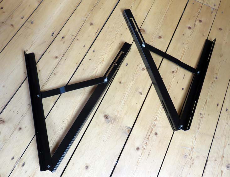
With this aluminum universal module mount, you can put the 100W module on the floor or anchor it to a wall with different set tilt angles. The tilt range for floor mounting is from 10° – 45° for wall mounting from 45° – 80°. Screws and other components are included.
* Affiliate Link - Last updated prices on 2024-04-18 / Picture source: Amazon affiliate program
Installation of the Solar Set
Now that I’ve introduced you to the components of the solar set, it’s time to install the solar system.
IMPORTANT: When you install the solar system, you are working with live components! If you have no experience with this, get a specialist company to help you with the installation. Working under voltage is dangerous!
Outdoor – Solar Module Structure
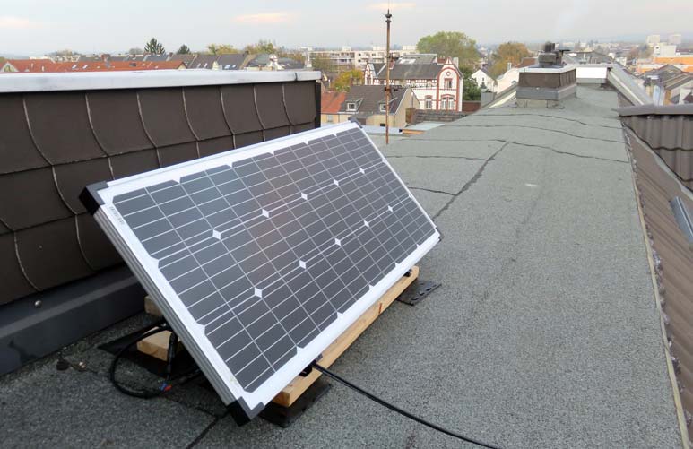
To assemble the solar panel I got help from a roofer friend, since I didn’t trust myself to mount it on my roof. After assembling the universal mount I passed all the parts on the roof for further assembly so that the assembly could continue there.
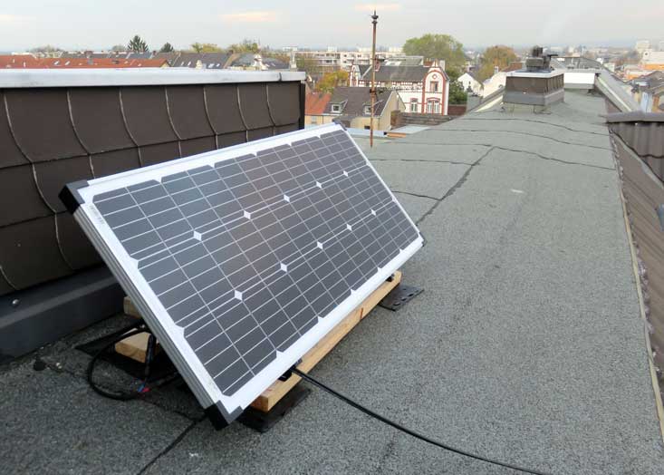
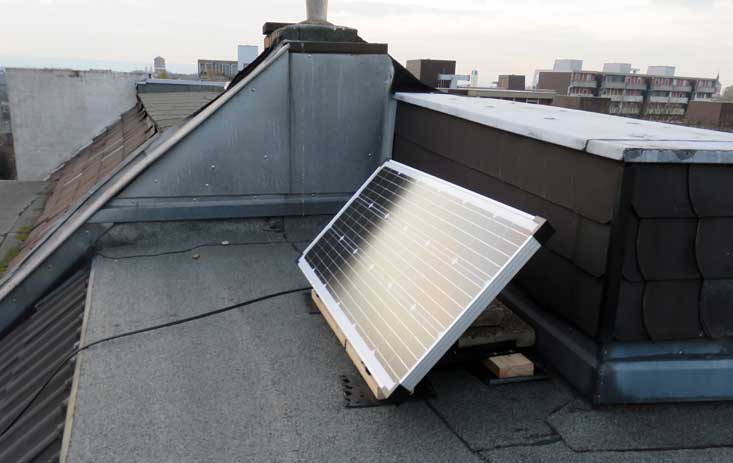
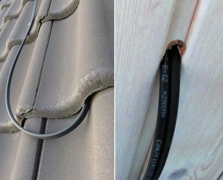
We routed the module connection cable up to a slanted skylight in my apartment and lifted a roof tile there. We routed the cable through the pre-roofing, insulation and vapor retarder and then pushed it through a hole in the interior cladding. Afterwards, we were able to professionally close the holes in the diffusion-open pre-roofing as well as the vapor barrier and the roof tile could be put back in place.
Note: Please remember to connect the module connection cable to the solar module only after the cable has been laid so far that it can be connected to the solar charge controller. As soon as the module connection cable is connected to the solar module, it is live!
Indoor – Wiring and Connection of Individual Components
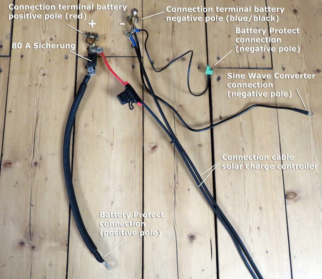
For the wiring of the individual components with a Battery Protect there is an assembly instruction from the manufacturer Victron Energy, which is not so easy to understand from my point of view (Figure 12). Therefore, I have traced the assembly instructions again more understandable for me in Figure 13. Since I do not use the connection on the charge controller for directly connected consumers, this is not considered in the drawing.

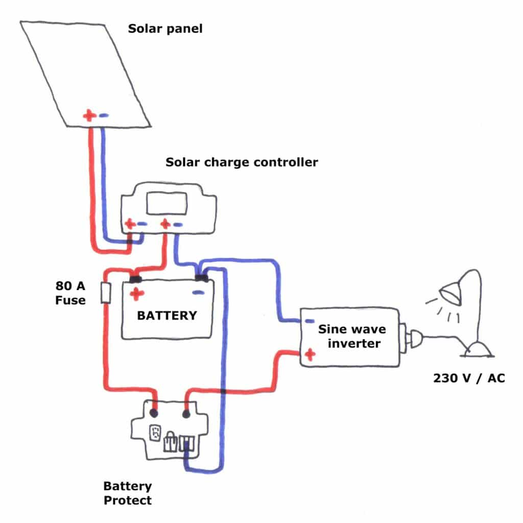
Before you start with the connection, you can partially pre-assemble the cables. The whole thing will look something like this:
Now that the cables have been pre-assembled, we can start commissioning the solar system.
IMPORTANT: The connection sequence must be explicitly observed, otherwise damage to individual components may occur! Please refer to the commissioning instructions again.
Connection sequence:
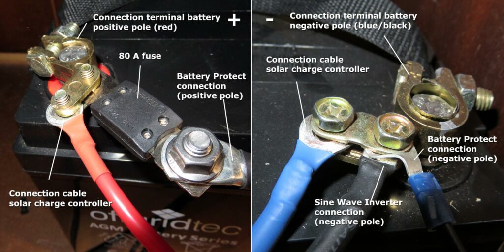
Step 1: Connecting the battery to the charge controller – first plus then minus!
From the pre-assembled cable, first connect the “Battery connection terminal” to the positive pole of the battery. Then the positive pole of the connection cable for the solar charge controller is connected to the solar charge controller. In the next step, the negative pole is connected to the battery and then to the negative pole of the solar charge controller.
Step 2: Connecting the solar module to the solar charge controller – first plus then minus!
To do this, connect the cable to the solar module and then to the solar charge controller.
Step 3: Connect the voltage transformer with interposed Battery Protect to the battery – first plus then minus.
IMPORTANT: The voltage transformer must be switched off. Make sure that this is the case.
Important notes from the manufacturer:
- When uninstalling, the reverse order must be followed, as the automatic adjustment does not work for systems 12V / 24V with a different connection order and the battery may be damaged. This will void the warranty.
- Operating the sine wave inverter directly via the solar charge controller can lead to its destruction. It is therefore recommended NOT to connect the voltage transformer directly to the solar charge controller.
Solar Set Operation
Setting on the Solar Charge Controller
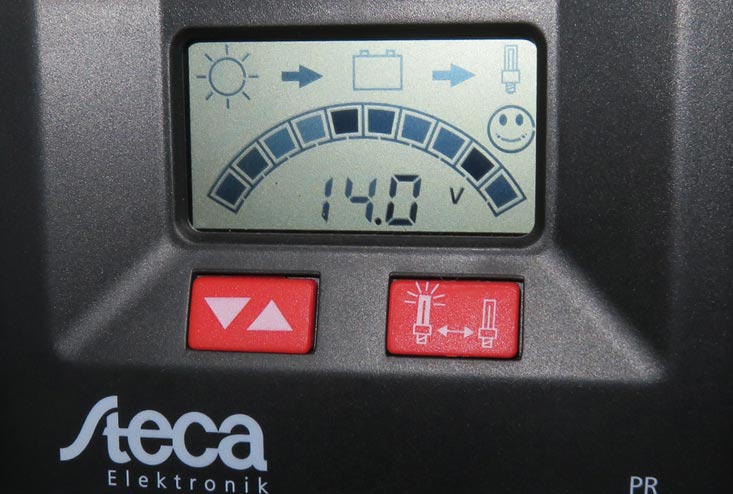
After you have connected everything, the solar system is ready for use. Now you need to make a few settings on the solar charge controller. The operating mode of the Steca 2020 solar charge controller must be changed from “SOC” to “Vol” with bar graph. This is the only way to ensure that the displayed state of charge of the battery is also displayed correctly.
If this is not done, the current drain cannot be detected. This results in the controller incorrectly displaying 100% full in SOC mode, although the battery may only be 50% charged. In “Vol” mode, the voltage is displayed.
In Figure 18 we have a fully charged battery with a displayed battery voltage of 14V. In this case the voltage transformer was not switched on.
Programming the Battery Protect BP-65
Note: As mentioned in the introduction to the Battery Protect, the new Smart BatteryProtect BP-65* has an integrated Bluetooth interface so that all required on/off thresholds can be configured, monitored, updated and diagnosed via the Victron Connect app (Google Playstore and Apple Appstore).
* Affiliate Link - Last updated prices on 2024-04-19 / Picture source: Amazon affiliate program
Next, we carry out the programming on the Battery Protect BP-65. The following settings are recommended for this purpose:
- AGM battery: 6B or better 7B (7 corresponds to a depth of discharge of 25%).
- Lithium battery: 8B (shutdown due to undervoltage in 12V system at 12V and restart due to undervoltage at 13V in relay mode).
Since in my case an AGM battery is in use, I have programmed the Battery Protect to 7B. How this works is explained very well in the following video from minute 2:04. In the manual of the Battery Protect you can find the respective performance data of the different programming states.
You first remove the remote jumper on the Battery Protect and then use a single insulated cable with open ends for programming.
One end is connected to the negative terminal of the battery and the other end of the cable is inserted into the programming port of the Battery Protect. Now the switching states are played through. Breaking the contact switches between numbers and letters.
Switch on Sine Wave inverter
After you have set everything, you can now connect a device to the sine wave inverter, turn it on and enjoy solar power.
My setup does not look super professional now, but everything works and I am happy. On the picture you can see that the lamp has a power consumption of 45.2W and the battery has a voltage of 13.9V.
To measure the power consumption I used an No products found.. The voltage reading on the charge controller can always differ a little from the monitor*.
Usability and Installation
The setup of the solar system was not really easy from my point of view and the instructions for the setup were not self-explanatory. I had to do a lot of research to understand the system and to know what, where and how to connect. Also the circuit diagram of the Battery Protect was not really clear to me when I first looked at it.
The exchange with colleagues from electrical engineering helped me significantly here, as they improved or shared my thoughts. For people without a technical background, the setup is definitely a challenge. Involving a specialist company should therefore be considered from my point of view.
The operability of the Steca solar controller, on the other hand, is easy to understand. A look at the very clear operating manual for the Steca 2020 should clarify many questions that come into question for the settings and modes.
Control behavior
The fact that a solar system does not provide an infinite amount of electricity should be made clear from the beginning. This becomes particularly clear in the following scenario. In summer, on hot days, it often happens that the temperature protection of the sine wave inverter takes effect and cannot be used at the moment of the highest power yield.
A cooling fan is installed in the sine wave inverter itself. However, this does not react when the temperature is exceeded – even though this is stated on various pages on the Internet (temperature-controlled cooling). The heat protection only takes effect when a certain power consumption is exceeded. If I am wrong here, please correct me.
On the other hand, the fan for cooling the sine wave inverter is already switched on at a power consumption >70W and results in a sound power of about 65 dB, which is really loud. Since the sine wave inverter is located in my living room, I always tried to stay below the threshold of 70W, since you can hardly understand your own words when the fan is running. Utilizing the spectrum of up to 600W is thus as good as impossible.
Result after one year: electrical energy generated
Which components had I connected to the solar system?
Since the fan is quite loud, I always tried to stay below a connected load of 70W. In total, I was then at about 55W connected load. With this I supplied the following consumers with power:
- Laptop in charging mode (approx. 9.6W)
- Monitor (21,2W)
- Distribution socket with 2 external hard drives and USB distributor (24.3W)
How much energy can the solar system produce?
According to the manufacturer, the average daily yields of the Autark S-Master 100W are as follows:
- average daily yield March to October* 400Wh (8 months)
- average daily yield November to February* 60Wh (4 months)
- Battery capacity at 50% (SOC): 642Wh (100%=1284Wh)
The solar set is theoretically capable of generating an electrical energy of about 105 kWh per year. At a voltage of 12V, this corresponds to an electrical charge of 8.75 kAh.
How much electrical energy could I generate?
A look at my solar charge controller shows that the total amp-hours charged in my battery in 2018 is 4.9 kAh. At a voltage of 12V, this equates to 58.8 kWh of electrical energy generated. This puts me 44% below the average annual yield for the solar set.
What could be the reason for this? Since I do not feed into the public grid with my solar set, the daily yield is only used for charging the battery. If the battery is full, the battery is not charged further. So if I have no active consumers connected to the solar set, no energy is consumed and the battery must be charged accordingly less.
Since I did not always have my electrical consumers connected to the solar set, I consumed correspondingly less energy. Reasons for this included the frequent switching off of the sine wave inverter in the summer due to overheating. Furthermore, it is very difficult to get the battery fully charged in the winter months when consumers are connected. With the stated average daily yield of 60 Wh in the winter months, you can’t really run anything. I am therefore quite satisfied with my result of about 58.8 kWh.
Conclusion
Positive features
It’s pretty cool to have a solar system on the roof and generate your own electrical energy. What convinced me about this complete set is the quality and price of the components. For just under 600€ you get a complete solar set and can produce your own electricity. This is easily enough to power a complete workstation (laptop, monitor, external hard drives and more). The quality of the components is also convincing. They seem safe, well-made and durable.
Another strong factor is the composition of the complete set. Everything has been thought of here! Especially as a beginner, it is almost impossible to think of all the components that are needed for a complete system. For me, this complete set is the optimal entry into the topic of photovoltaics.
Negative properties
What did not convince me is the sine wave inverter (old version from Solartronics) on the one hand and the assembly instructions on the other. According to the manufacturer, the sine wave inverter needs the following conditions: 0 – 40 °C at max. humidity of 70 %, non-condensing. At room temperatures around 40 °C the surface temperature of the voltage transformer can reach up to 60 °C. At surface temperatures >60 °C, an automatic shutdown then takes place.
Sine Wave Inverter
In summer it is quite common for temperatures of 40 °C or more to be reached indoors. However, it is difficult to use the sine wave inverter in these moments, as the overheating protection takes effect. In my experience room temperatures > 34 °C are also sufficient here and the sine wave inverter switches off due to overheating.
On the one hand, this is very important because safety comes first. On the other hand I do not understand why there is no retrofittable cooling system for the sine wave inverter and why the cooling fan only turns on when a certain power consumption is exceeded (about >70 W). In my opinion there is room for improvement here.
Assembly Instructions
In my opinion the assembly instructions are not optimally designed for beginners and a technical background is a great advantage. I do not come directly from the electrical engineering and have therefore exchanged with colleagues, who then helped me with advice. Especially the integration of the Battery Protect in the solar system, which is explicitly recommended, was not completely clear and understandable for me at the beginning. Here I would wish for better instructions.
Test Rating
Rating: Offgidtec Autarkic S-Master
This Offgidtec Solar System Autarkic S-Master complete set is very suitable for campers, garden and van owners. But also techies and beginners will get their money’s worth. You get a complete package at an unbeatable price, with very good components and a lot of fun when the first solar power can be enjoyed.
For apartment and house owners, this system is rather unsuitable, because it is too small and power-intensive consumers can not be connected. Homeowners should therefore consult with a specialist solar installation company and explore the possibilities on site.
Summary
ADVANTAGES: Scope of the complete package is very good, Price-performance ratio, Products quality, Perfect starter kit
DISADVANTAGES: Technical background for the installation is recommended, Control behavior not optimal, Rapid overheating of the sine wave inverter
Go to shop*
Below I have listed all the components once again.
* Affiliate Link - Last updated prices on 2024-04-19 / Picture source: Amazon affiliate program
I hope I was able to provide you with some valuable information about the solar complete set “Autark S-Master” and help you with your purchase decision. If you have any questions, suggestions or criticism, please use the comment function, I look forward to it.
Greetings Martin
Further links and sources:
Wikipedia – Tempered Solar Glas
Wikipedia – Eloxal Process
Photovoltaik.org – Bypass Diode
AMSolar – Battery Protect 65
Victron Energy – Battery Protect
